

something about RC Servos(2)
Digital RC Servo Operation
Digital servos to the rescue! Like I said before, a digital servo has all the same parts as an analog servo, even the three wire plug that plugs into the receiver is the same. The difference is in how the PWM signal is processed and sent to the servo motor.
A small microprocessor inside the servo analyzes the receiver signals and processes these into very high frequency voltage pulses to the servo motor. Instead of 50 pulses per second, the motor will now receive 300 and up pulses per second.
The pulses will be shorter in length of course, but with so many voltage pulses occurring, digital servos have much improved deadband, better resolution, faster response, quicker and smoother acceleration/deceleration, and immensely better holding power.
You can test this very easily by plugging in a digital servo and an analog servo to your receiver. Try to turn the servo wheel off center on the analog RC servo.
Notice how you will be able to move it slightly before the servo starts to respond and resist the force - it feels a bit "spongy".
Now do the same thing with the digital RC servo. It feels like the servo wheel and shaft are glued to the case ¨C it responds that fast and holds that well.
Incidentally, if you have ever wondered why digital servos "sing" when very light force loads are placed on them, what you are hearing is are the higher frequency voltage pulses acting on the motor at about 300 Hz.
Digital Servo Draw Back
Now nothing is perfect and this increase in speed, torque, and holding power does come at a cost. Power Consumption!
Yup, digital servos are power hungry. All those hundreds (thousands) of power pulses per second use up more battery power than an analog servo would. This really is not that much of a problem these days since RX battery packs have at least double or triple the capacity of what the same size/weight pack had just a few years ago. That said, it can be a big issue for your BEC (internal or external) or a voltage regulator all of which have a finite maximum current output. For more information about this potential problem, please see the Digital Servo article.
So yes, digital RC servos are much better than analog. You can still fly a flybared RC helicopter with analog cyclic servos, but once you switch over to digital, you will likely never go back. DonˇŻt forget about that heading hold gyro or electronic flybarless systems. As I said, most if not all these days need to be paired with fast digital servos to work correctly ¨C no exceptions!
One last point I should clarify with this whole analog/digital RC servo discussion. Remember those speed and torque specifications I talked about earlier... You will find analog servos that have better speed and torque ratings than some digital servos; so why not get one of them over a more expensive slower digital?
Remember, the analog servo is slow to respond and provides little torque during small, fast command inputs not to mention poor holding power. Those good looking specifications are given at full stick movement when the servo has ramped up to full speed and torque. The slower spec digital servo in this case will still provide much more speed and torque where it's needed most.
RC Servo Motor Types
Brushed, Coreless, Brushless

3&5 Pole Brushed RC Servo Motors
Most low cost / standard servos (analog or digital) use what is called a brushed 3 pole electric DC motor.
This is just a standard 3-pole wire wound DC motor with a 3 conductor commutator being energized by two opposing brushes feeding positive & negative current ¨C the most common type of DC motor in existence.
One step up from the 3 pole is the 5 pole servo motor. As you can imagine, two more wire windings will give a 5 pole motor quicker acceleration and more torque on start up. You know by now the faster the servo ramps up to speed and the more torque it produces; the better it is for most helicopter applications.
Well, improving the electric motor itself will produce more speed and torque too; coupled with digital technology, the resultant speed and torque are indeed impressive. Still, a 3 or 5 pole motor no matter analog or digital power, is limited by its high rotational mass... Time to go on a diet!
Coreless RC Servo Motors
A standard 3 or 5-pole wire wound servo motor uses a steel core with wires wound around the core, with the commutator at one end. This "armature" spins inside the motor body which has permanent magnets attached.
As you may recognize, that big armature core, commutator, and all that wire weighs a fair bit and has a good deal of rotating mass. When voltage is applied to turn the motor, it has to first overcome this weight to get things turning ¨C it is slow to accelerate (due to inertial mass). Once up to speed, it also continues to turn for a while when the voltage is removed ¨C it is slow to decelerate or reverse direction (again due to higher inertial mass). This is also quite hard on the brushes and commutator.

In a Coreless design, the heavy steel core is eliminated by using a light weight wire mesh that spins around the outside of the magnets within the body of the motor.
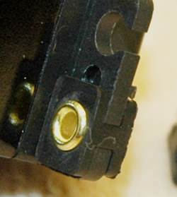
This picture of a coreless servo motor I opened up shows the parts quite well.
It's kinda hard to see inside the motor can/body, but that center piece in the middle contains the N/S magnets that the coreless wire mesh spins around. The wire mesh rotating armature is simply made from thin copper wire strands along with the motor shaft and commutator on the back end.
The coreless motor armature weighs a fraction of what a wire core wound does. This results in quicker acceleration and deceleration. The result is more available torque, and faster response time.
I personally feel coreless motors offer the best servo performance - even over brushless (at least from the stand point of fastest acceleration and least amount of deadband).
Brushless RC Servo Motors

The latest advancement is to use a small brushless motor in the servo.
This is the exact same principle and has the same advantages all us electric powered RC'ers have come to expect out of our big brushless motors that are used to power our planes, helicopters, quad rotors, cars, buggies, & boats.
If you are wanting the best efficiency, smoothness, and lifespan; ante up the coin and go for brushless. I personally run brushless exclusively on my two largest & most costly birds and run coreless on everything else. I've been very happy so far with that compromise.
One other consideration is the tail servo. It has to move back and forth even more and faster than the swashplate servos to keep the tail locked, so it has a more demanding workload when it comes to revolution changes & motor rotations.
You will therefore often see people using brushless tail servos, along with conventional brushed or coreless servos on the swashplate as a budget driven compromise. I have also done this with excellent results.
How To Reverse RC Servos?
You can also reverse many RC servos yourself for free, very easily by swapping the motor wires and potentiometer wires from side to side.
RC Servo Bearings, Metal Gears, Splines, Cases, & Water Resistance
RC Servo Bearings
You will notice when servo shopping, many specifications list if the servo has bearings and the number of bearings ¨C usually 1 or 2. These bearings are used on the main servo output shaft instead of a simple bushing.

The advantages of having ball bearings on the output shaft in a servo are pretty much the same as I talked about in the Bearing Section of best RC helicopter features ¨C less friction and slop.
Because of the many vibrations and mechanical loads placed on the servo in RC helicopters & RC car/buggy steering, non bearing servos do develop slop very quickly and of course this makes control more sluggish and vague feeling.
Most quality RC servos, even lower cost ones these days will come with at least one bearing ¨C this will be located on the servo output shaft where it exits the servo, this is where most of the side loads will occur. Better more expensive servos will use two bearings to further improve overall slop free performance.
Metal Gears & Metal Output Shafts

With today's high torque and speedy digital servos, combined with high force load RC model applications, metal gears and output shafts are getting more and more common place.
On the heli side of the hobby, they are pretty much industry standard these days.
They are a popular choice for several reasons, but improved strength is the obvious one. There are three downsides to metal gears however. They weight a little more than plastic or nylon gears, they wear out a little faster, and they are more expensive to replace.
Yes, most servos have replaceable gear sets so you can easily replace the gears, but some metal gear sets are approaching half the cost of just getting a new servo.
The best metal gear servo's on the market these days are using titanium or various exotic titanium alloy gear sets and this drops the weight down and improves gear wear characteristics substantially, while increasing the cost as well.
All that said, don't think for a second that by using metal geared servos, you will never strip out a gear set.
I've actually been stripping out more metal gear sets lately than I ever did with plastic! This is not due to the servos however, it's because our RC helicopters have changed so much.
Most are flybarless so any blade impact energy is no longer partially absorbed through the mixing of the flybar. Many are also DFC, so again, more direct force is transmitted.
Following the "direct" trend, most helis now have direct servo to swashplate linkage attachment, instead of using bell crank linkage arrangements which provided a fair amount of "mechanical fuse" protection.
Lastly, more of us are using very stiff & strong metal servo arms/wheels (one less mechanical fuse point) and rigid mounting our servos with no more grommet dampening.
Add all these factors together and servos are now exposed to much higher transmit forces from even a mild blade strike than ever before.
Yep, the exact same reasons manufacturers are designing all these direct linkage layouts work both ways.
Your servos will transmit more force and power direct to the rotor blades; but the rotor blades will also transmit their impact forces direct back into the servos with none of the "impact filters" we used to have.
I suppose this is progress, but when you are shelling out $70 bucks + for a servo and $30+ for a replacement gear set, I have to ponder if this is really the direction the average RC helicopter pilot wants or needs?
RC Servo Grommets

Seeing that I just mentioned "servo grommets", I may as well touch on them since I get the occasional question of why, when, and how to use them.
As I just explained, today's trend, especially with electric powered helicopters, is to rigid bolt the servo direct, and not use grommets at all.
For the performance driven hard core 3D pilot, that makes sense, but I still use them on all my helicopter servo installations (both cyclic & tail).
I simply don't need all that "rigid" connectivity for my flying style, and would rather give my servos a little extra dampening protection. Grommets just cushion the servo a little bit to help absorb some vibration energy from getting into the servo, and perhaps a wee bit of impact energy as well. They are almost always used on fuel powered helicopters due to the higher vibration environments.
RC servo grommets come in two flavors, square and round.
Square are the most common, but both types have the same purpose and are installed onto the servo the same.
You simply slide them into the mounting holes through the slot on the holes. You also need to fit the brass sleeve into the rubber grommets so the mounting screw or bolt can't tear the rubber or tear the grommet right out of the servo mounting hole.
I usually install my brass sleeves upside down in the grommet, but that is just my method; it seems to work both ways just as well.
Depending on how tight you snug down the mounting screws/bolts, the more or less dampening you will get. On electric powered helis, I generally compress the grommets a moderate amount. On fuel powered where I want more dampening, just snug enough to keep the servos tight. Main thing is all 4 mounting screws/bolt (or 2 on micro size servos), are tightened about the same amount to achieve even grommet compression/dampening.
RC Servo Splines

All RC servos (other than linear types) have a "splined" output shaft. The primary reason for this is so the servo arm or wheel can't slip out of position under the large torque loads it's exposed to.
The secondary reason for using splines is to help you fine tune your servo arm & wheel position. I go over this feature and how to use it in mySwashplate setup ebook in detail, but it's such a useful tool we have at our disposal to make RC heli setup both easier and more accurate.
The thing to know with servo splines, is there are different sizes of splines and numbers of teeth on the spline.
You may for example get an RC helicopter or car kit that comes with servo arms or wheels, go out and get the correct size, torque, and speed rated servos, only to find you can't fit the arms that came with your kit onto the servos - AAUGH!
For most servos other than the small minis & micros, spline type is shown by a number (number of spline teeth) followed by a "T".
The most common out there is 25T. These are often called Futaba splines as most Futaba servos use them; but so many others do as well such as Align, BK, Blue Bird, KST, MKS, Power HD, Savox, Traxxas, Turnigy...
In other words, when in doubt, you are going to be right more times than wrong choosing 25T.
The next most common are 23T servos and arms/wheels. Spektrum & JR are the primary users, along with airtronix and a few others.
Hitec is the odd ball or should I say even ball. They use 24T.
Water Resistant/Dust Proof RC Servos
Some servos are sealed to prevent water and dust from seeping inside. The case halves have gaskets, there is an o-ring around the output shaft, and there is silicone sealant where the wires exit the servo case.
Now this is obviously a good servo feature for RC boating or for your monster truck when you drive it through the old mud hole. It is however unlikely you will be flying your heli under the water, through the mud, or during a dust storm. If you are, you have bigger problems to deal with than contaminated servos.
That said - water resistant/dust proof RC servos do make sense with nitro RC helicopters or any nitro model that exposes the servo to nitro goo . If your RC servos are coated in nitro goo, it will eventually seep inside the servo. This wonˇŻt be a problem for the gears, but will play havoc with the circuit board, potentiometer, and electric motor over time.
RC Servo Body Material
There are 3 primary types of RC servo cases or bodies in production these days: Plastic, Aluminum Plastic Combination, Full Aluminum. Prices go up in that order as well.
Due mainly to digital servo technology, we started seeing the motors running much hotter than with analog. By using an aluminum center section (the section where the motor and electronics are located), that extra heat can be dissipated through the aluminum - its main purpose is to act as a heat sink.
Most quality digital servos today, other than micro size ones, will have either the mid section or the full servo made from aluminum. The full aluminum servos are of course stronger, but heavier and of course more expensive than their "combo material" counterparts.
The one thing to appreciate with any aluminum cased servo (combo or full), is for the aluminum to act as a proper heat sink, the motor has to be in direct physical contact with the center case section. I've opened up some cheap no-name aluminum servos to find the motor isn't even close to touching the inside of the case.
These are aluminum "bling" servos, next to no practical heat dispersion whatsoever.
The latest method is to then machine cooling fins into the case to further improve heat dissipation, not to mention shed some of that extra aluminum weight! Very pretty, and not just bling...A good heat sinked servo case will actually be molded or machined internally to wrap part way around the motor for good heat conductivity from the motor to the case.
TAG:
{aspcms:comment}